Headlight Board Pin-out and Test Points
Table of Contents
Tools in this guide
- Multimeter with DC voltage mode
Click Here for a guide on how to use a Multimeter, and where to buy one.
Connector Part Numbers
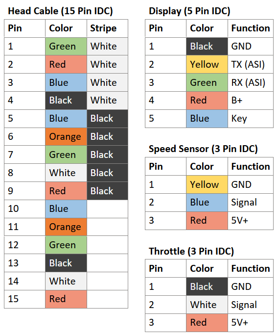
15 Pin IDC Connector: TE Connectivity 4-643814-5
5 Pin IDC Connector: TE Connectivity 3-640441-5
3 Pin IDC Connector: TE Connectivity 3-640441-3
2 Pin IDC Connector: TE Connectivity 3-643814-2
(IDC = insulation-displacement contact)
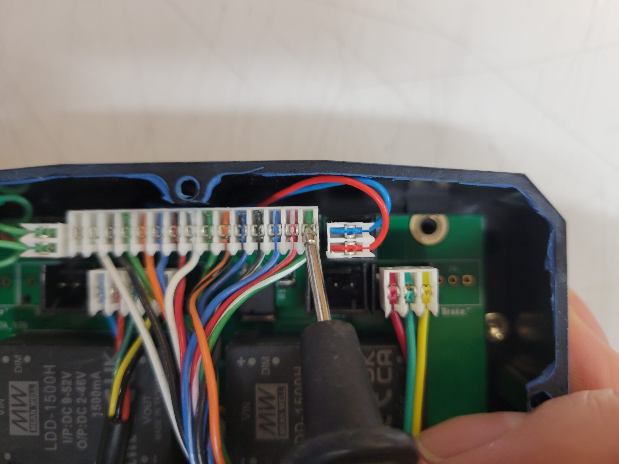
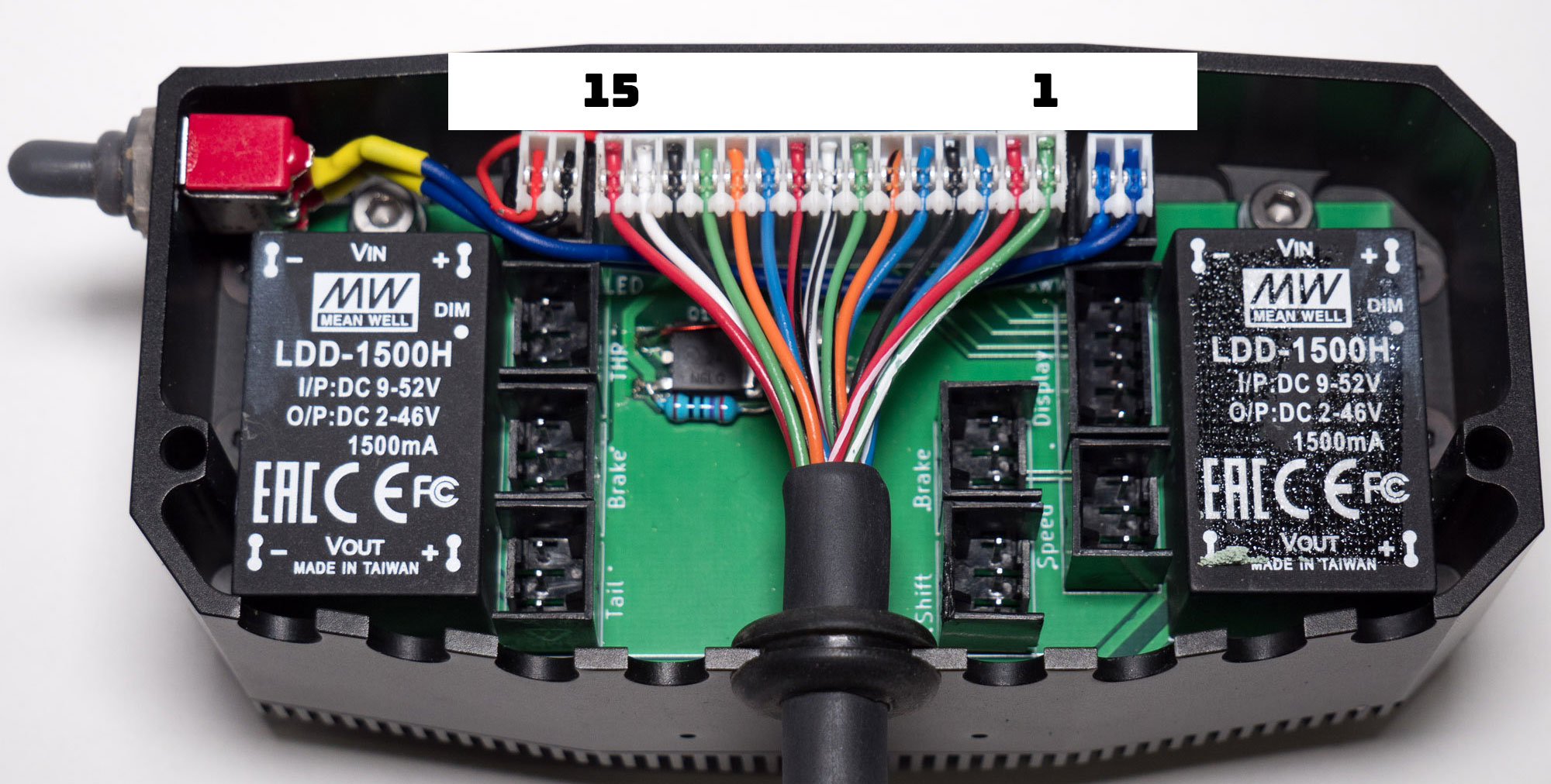
When looking at the connectors as shown from the back of the headlight, the highest pin number is on the left and pin 1 is on the right. The pin numbers are also molded into the plastic of the connector body.
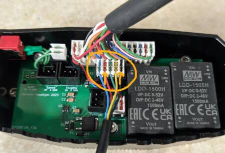
To probe these pins, leave the connector attached to the headlight, and place multimeter probes on the back of the connector, you will see metal tabs sticking up around the wires, place the probes on those metal tabs.
Use caution when probing the connector that you do not let the probes touch and create a short circuit.
Diagnostic Tests
Display does not turn on
Make sure your battery switch is on, and that it is at least partially charged (see how to check by clicking here)
5 Pin Connector – Display Power Supply
Pins 1 (Black) and 4 (Red)
This should read battery voltage which will be between 33V and 60V, depending on bike model and state of charge.
Display turns on, but the Motor does not run
Turn the bike and display on.
15 Pin Connector – 5V Supply
Pins 1 (Green / White) and 2 (Red / White)
This should read around 5V.
15 Pin Connector – Throttle
Pins 1 (Green / White) and 8 (White / Black)
This should read around 0.9V when not touching the throttle.
Turn the throttle and the voltage should rise, up to around 4.2V at full throttle.
Error 22 on the Display (Throttle Error)
Turn the bike and display on.
15 Pin Connector – Throttle
Pins 1 (Green / White) and 8 (White / Black)
This should read around 0.9V when not touching the throttle.
Headlight does not work
Turn the bike and display on, then hold the “UP” button until the headlight symbol activates on the display (or with the MMI, tap the headlight toggle).
15 Pin Connector – Headlight Power Supply
Pins 11 (Orange) and 12 (Green)
This should read battery voltage which will be between 33V and 60V, depending on bike model and state of charge.
15 Pin Connector – Headlight Trigger Signal
Pins 1 (Green / White) and 10 (Blue)
This should read around 6V.